Configuration
Select File → Configure to display the configuration dialog:
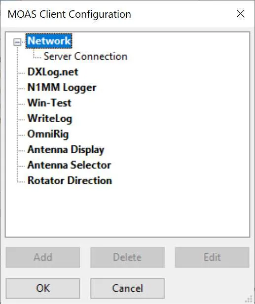
This shows the various things that can be configured. It is not necessary to configure all of them. For example you might run this on the computer where your logging program is running and configure only a logging program interface.
Some items, such as the logging interfaces, can only have one copy. Some, such as antenna selection, can have several. There will always be one network interface. If an item only allows one copy the Add button will be greyed out when there is one copy.
Network Interface
Section titled “Network Interface”The network interface connects the MOAS Client to the server. There must be one network interface. It needs the IP address and port number of the MOAS Server.
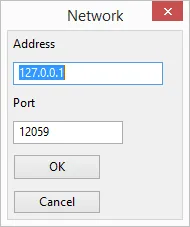
If the server is running on the same PC as the client then the default address will probably work. Otherwise it must be the IP address of the PC that is running the server.
The default port number is the same as the default for the server. You should not need to change it unless you have changed the server port number.
Logging Program Interfaces
Section titled “Logging Program Interfaces”The MOAS Client can interface with the most popular contest logging software.
The server refers to all radios by the station number and radio number. The interface must be configured so that it knows which station number and radio number to use when it sends frequency or antenna direction information to the server.
In a single operator station usually the server is configured so the only station is station 1 and the radio is radio 1 or if SO2R the radios are radio 1 and radio 2. For a multi-op usually each computer running a logging program is given a different station number.
Configuring a logging program interface involves specifying the station and radio numbers to use and providing whatever information is necessary for the MOAS Client to receive information from the logging program. The latter information is different for each logging program.
It is recommended that the logging interface be run on the same PC as the logging program. Otherwise some capabilities will not be available and reliability may suffer. For WriteLog and OmniRig the MOAS Client with the logging interface must be run on the same PC as the logging program.
DXLog.net
Section titled “DXLog.net”The client works with DXLog.net 2.4.15 or later.
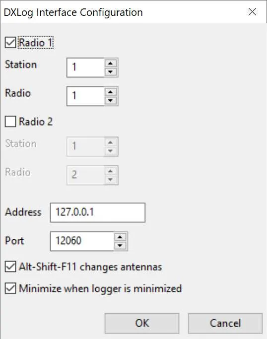
Radio 1 and Radio 2
For normal SO1R or SO1V operation select Radio 1. Select both Radio 1 and Radio 2 for SO2R when the logging program is controlling two radios.
Set the station and radio numbers to the numbers the MOAS server uses for these radios.
Address and Port
The address and port must be in the list of addresses and ports set for Radio UDP broadcast in DXLog. If DXLog is going to change antenna direction then the address and port must be in the list of addresses and ports set for Direction UDP broadcast. These are set in the Network Parameters dialog which is accessed through the NETCONFIG command or the Options menu. Also Radio information and Antenna Direction must be checked in the Broadcast section of the Options menu.
Alt-Shift-F11 changes antennas
If Alt-Shift-F11 changes antennas is checked then pressing Alt-Shift-F11 in DXLog will change to the next antenna.
N1MM Logger
Section titled “N1MM Logger”The client works with N1MM Logger and with N1MM Logger Plus. Not all features are available with the older N1MM Logger.
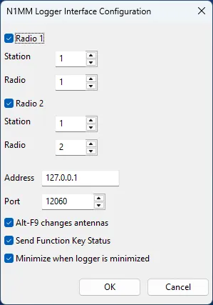
Radio 1 and Radio 2
For normal SO1R or SO1V operation select Radio 1. Select both Radio 1 and Radio 2 for SO2R when the logging program is controlling two radios.
Set the station and radio numbers to the numbers the MOAS server uses for these radios.
Address and Port
The address and port must match those in N1MM Logger.ini. The values shown are the defaults.
Alt-F9 changes antennas
If Alt-F9 changes antennas is checked then pressing Alt-F9 in N1MM Logger will change to the next relative antenna. This requires some configuration in N1MM Logger.
Two antennas must be configured in the Antennas tab of the N1MM Logger Configurer. They do not need names or anything else. But they must include the bands where Alt-F9 will be used. This is an example which will work for any antennas on 80–10 metres. The number of antennas available has nothing to do with the number of antennas configured in N1MM Logger. This configuration will cycle through any number of available antennas.
Note: If the logging program is set for SO2R then three antennas must be configured this way.
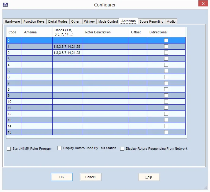
Alt-F9 is very effective if two antennas are available for a band. It will work with any number but it becomes cumbersome if more than about four antennas are available.
Send Function Key Status
When N1MM Logger transmits it broadcasts the F-key pressed. If Send Function Key Status is checked then the function key information is sent to the MOAS server. The server sends it to the appropriate clients which can display it in the Antenna Selector windows.
Minimize when logger is minimized
If Minimize when logger is minimized is checked then when N1MM Logger is minimised the MOAS II Client will minimise all Antenna Display, Antenna Selector, and Rotator windows. They will be restored when N1MM Logger is restored. This only works if the client and logger are running on the same PC.
N1MM Logger broadcast configuration
N1MM Logger does not normally broadcast the information needed by the MOAS Client. Add this to N1MM Logger.ini:
[ExternalBroadcast]DestinationIPs=127.0.0.1DestinationPort=12060IsBroadcastRadio=TrueThis assumes that N1MM Logger and the MOAS Client are running on the same PC. If not, change the DestinationIPs line to include the IP address of the PC where the MOAS Client is running.
Win-Test
Section titled “Win-Test”This works with Win-Test V4. It has not been tested with earlier versions.
If the client is not run on the same PC as the logging software it will not be able to determine which radio is active in SO2R configurations.
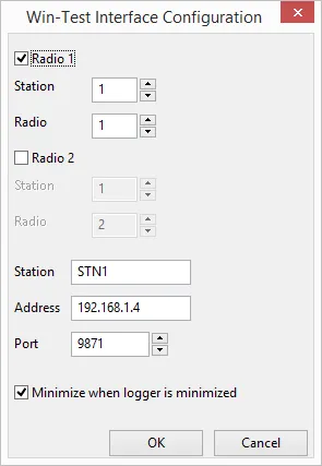
Radio 1 and Radio 2
For normal SO1R or SO1V operation select Radio 1. Select both Radio 1 and Radio 2 for SO2R when the logging program is controlling two radios.
Set the station and radio numbers to the numbers the MOAS server uses for these radios.
Station address and port
The address should be the address of the computer which is running Win-Test.
The client may set the address for you. If not, or if it sets the wrong address, there are several ways to find the correct address. One way is to start a command window and type the IPCONFIG command. Look for the IPv4 Address. This is what you want unless you have a complex network topology.
If your computer has virtual networks or multiple active network interfaces then you should pick the network which matches the broadcast address Win-Test shows in the Interfaces Configuration dialog.
The port number must match the port number specified in the Win-Test Interfaces Configuration dialog. By default this number is 9871.
Minimize when logger is minimized
If Minimize when logger is minimized is checked then when Win-Test is minimised the MOAS II Client will minimise all Antenna Display, Antenna Selector, and Rotator windows. They will be restored when Win-Test is restored. This only works if the client and logger are running on the same PC.
WriteLog
Section titled “WriteLog”This client works with WriteLog V11.23 or later. It works with older versions but this has not been tested.
The client must be run on the same PC as the logging software.
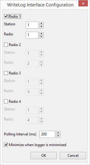
Radio 1, Radio 2, Radio 3, and Radio 4
WriteLog is capable of controlling up to four radios. For normal SO1R or SO1V operation select Radio 1. Select both Radio 1 and Radio 2 for SO2R when the logging program is controlling two radios. Select Radio 3 or Radio 4 if you have additional radios being controlled by WriteLog.
Set the station and radio numbers to the numbers the MOAS server uses for these radios.
Polling Interval
The polling interval controls how often the client checks the frequencies in WriteLog. A longer polling interval reduces computer overhead but will increase the time between changing bands and the server changing antennas.
OmniRig
Section titled “OmniRig”OmniRig is not a logging program. It provides frequency information to the MOAS Client. It can be used if a logging program is not being used or if the logging program does not control the radios.
This client works with OmniRig V1.15 or later.
The client must be run on the same PC as the logging software.
The Omni-Rig program must be run to configure the serial port interfaces and to set the radio type. Once this is done it is not necessary to start Omni-Rig because the MOAS Client will start the component it needs.
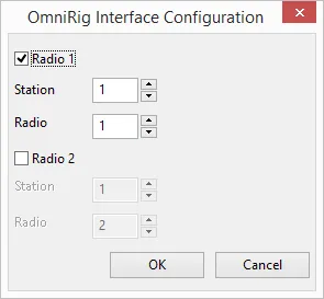
Radio 1 and Radio 2
If the computer is connected to one radio select Radio 1. Select both Radio 1 and Radio 2 if the computer is connected to two radios.
Set the station and radio numbers to the numbers the MOAS server uses for these radios.
OmniRig cannot provide focus information. If an antenna display, antenna selector, or rotator window is configured to show information for the radio with logger focus it will show Radio 1 unless Radio 1 is not checked, in which case it will show Radio 2.
Antenna Display Configuration
Section titled “Antenna Display Configuration”This is the dialog used to configure an antenna display:
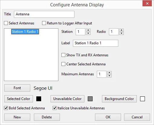
Set the Title text to the text you want to be shown in the title of the Antenna Display window.
Check the Select Antennas box if you want clicking on an antenna to select it if it is available.
Check the Return to Logger After Input box if you want the keyboard focus to be returned to the logging program’s active radio entry window when an antenna is clicked.
The Antenna Display window can show antennas for multiple radios. Each radio is displayed in a separate section. Click the New button to add a section. Click the section you want to configure in the list box. Click Delete to delete the selected section. The information to the right of the list box can be configured differently for each section:
- Set the Station and Radio boxes to the station and radio numbers for the station you want to show antennas for.
- Set the Label to the text that should appear above the antennas.
- Check the Show TX and RX Antennas box if you want to show both antennas when they are different in a window that is showing one antenna.
- Check the Center Selected Antenna box if you want the selected antenna to be displayed in the centre of the window section.
- Set Maximum Antennas to the number of antennas you wish to display. If you just want to display the currently selected antenna set it to 1. If you want to display all available antennas set it to the largest number of configured antennas you have on any band that you will use with this radio.
- Click the Font button to set the text font, size, and the colour to use for an antenna which can be selected.
- Click the Selected Color button to set the text colour to use for an antenna which has been selected.
- Click the Unavailable Color button to set the text colour to use for an antenna which cannot be selected.
- Click the Background Color button to set the background colour.
- Check the Bold Selected Antenna box if you want the selected antenna to be displayed in bold type.
- Check the Italicize Unavailable Antennas box if you want the antennas which cannot be selected to be shown in italics.
Antenna Selector Configuration
Section titled “Antenna Selector Configuration”This is the dialog that is used to configure an antenna selector:
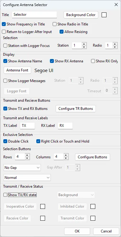
Set the Title text to the text you want to be shown in the title of the Antenna Selector window.
Click the Background Color button to set the background colour.
Check the Show Frequency in Title box if you want the frequency to be displayed in the window title.
Check the Show Radio in Title box if you want the radio number to be displayed in the window title.
Check the Return to Logger After Input box if you want the keyboard focus to be returned to the logging program’s active radio entry window when an antenna is clicked.
The selector can display the antennas for a specific radio. Or it can show the antennas for the radio that has the logging program focus. It can only show the latter if it is running on the same computer as the logging program. Check the Station With Logger Focus box if you want the selector to show the antennas for the station that has logging focus. Otherwise set the Station and Radio to the one you want to display.
Check the Show Antenna Name box if you want the antenna name to be displayed in the upper left of the selector window.
Check the Show RX Antenna box if you want to show the receive antenna when it is different from the transmit antenna.
Check the Show RX Only box if you want to only show the receive antenna name. This can be useful if the antenna selector is for a sub receiver.
Click the Antenna Font button to set the font, size, and colour of the antenna name text.
Check the Show Logger Messages box if you want to show messages from the logging program. N1MM Logger Plus will show the key pressed when transmitting a message. Set the Station and Radio to the one you want to display messages from. Click the Font button to set the font, size, and colour of the message text. Set the Timeout to the minimum amount of time the message should be displayed.
Check the Show TX and RX Buttons box if you want to add transmit and receive buttons to the upper right of the window. These buttons can be used to select an antenna for transmit only or receive only if the configuration allows this.
Click Configure TR Buttons to display a dialog where you can set the size, shape, colours, and font of the TX and RX buttons. See Transmit and Receive Buttons for details.
The TX and RX labels are the text for the TX and RX buttons. They are also used to label the transmit and receive antennas if antennas are being shown and the transmit and receive antennas are different.
Check the Double Click box if you want to be able to exclusively select an additive antenna by double-clicking a button.
Check the Right Click or Touch box if you want to be able to exclusively select an additive antenna by right-clicking a button or by touching and holding the button if it is displayed on a touch-sensitive screen.
Set the Rows and Columns for the button grid.
Click Configure Buttons to display a dialog where you can set the size, shape, colours, stripes, and font of the buttons. See Antenna and Function Buttons for details.
Select Gap After Row or Gap After Column if you want a larger gap between two rows or between two columns. Select No Gap if you do not want a wider gap.
Select Normal if you want the buttons presented as they are configured on the server. Select Rotate 90, Rotate 180, Rotate 270, Flip Vertical, Flip Horizontal, Rotate 90 Flip Horizontal, or Rotate 90 Flip Vertical to rotate or flip the layout.
Select Show TX/RX state if you want to show the transmit / receive state in the window. Select Background if you want the status to change the colour of the window background. Select TX Antenna if you want the status to change the colour of the background of the transmit antenna name. Select TX & RX Antennas if you want the status to change the colour of the background of the transmit and receive antenna names.
- Click Inoperative Color to set the colour when the server cannot communicate with the switch hardware.
- Click Inhibited Color to set the colour when the radio is inhibited from transmitting.
- Click Receive Color to set the colour when the radio is receiving and is allowed to transmit.
- Click Transmit Color to set the colour when the radio is transmitting.
Transmit and Receive Buttons
Section titled “Transmit and Receive Buttons”This is the dialog which appears when Configure TR Buttons is clicked:
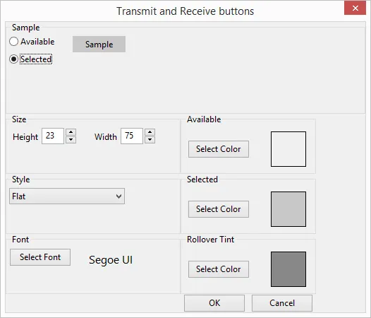
The default colour for Available may be the same colour as the dialog background which may be confusing when looking at the sample. Unless you set the Selector window background to this same colour it will not be a problem.
Select Available or Selected to set the sample button to the normal state or the state when it has been clicked.
Set the Height and Width to the desired size.
Select Flat, Flat Rounded, Flat With Border, Flat Rounded With Border, or 3D to choose the button style you prefer.
Click the Select Font button to set the font, size, and colour of the button text.
Click the Select Color button in the Available box to choose the colour the button should show when it has not been clicked.
Click the Select Color button in the Selected box to choose the colour the button should show when it has been clicked.
Click the Select Color button in the Rollover Tint box to choose the colour to tint the button when the mouse cursor is on it. Usually a light or dark grey is appropriate but any colour can be used. It is currently not possible to tint a pure white button.
Antenna and Function Buttons
Section titled “Antenna and Function Buttons”This is the dialog which appears when Configure Buttons is clicked:
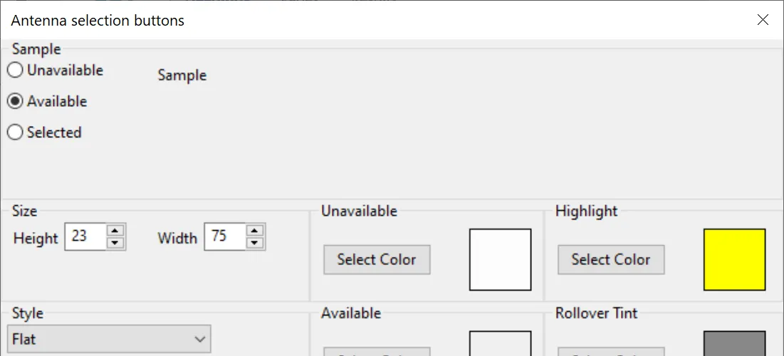
Select Unavailable, Available, or Selected to set the sample button to the antenna unavailable, antenna available, or antenna selected state.
Set the Height and Width to the desired size.
Select Flat, Flat Rounded, Flat With Border, Flat Rounded With Border, or 3D to choose the button style you prefer.
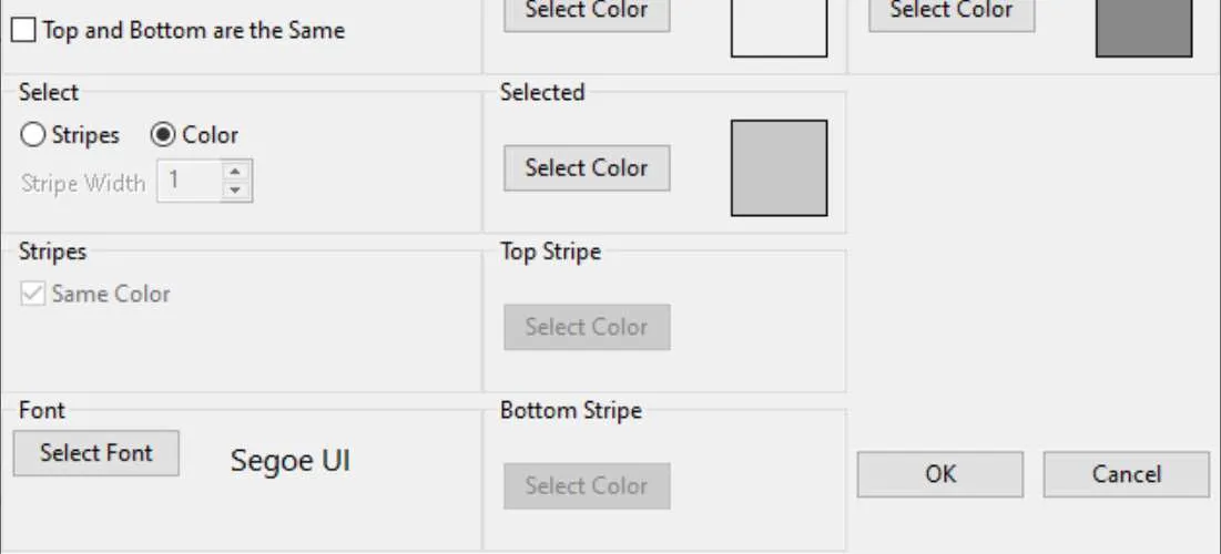
Check the Top and Bottom are the Same box if you want the status to be combined instead of having transmit on top and receive on the bottom. If this is checked the entire box will show the selected colour if the antenna is selected for either transmit or receive or the available colour if it is available for transmit or receive.
Select Stripes if you want the selected antenna to be indicated by a stripe on the button. Select Color if you want the selected antenna to be indicated by a different colour.
If you have selected Stripes then set the Stripe Width. A width of 1 is narrow, larger numbers are wider. If you have selected Stripes check the Same Color box if you want the top and bottom stripes to be the same colour.
Click the Select Font button to select the font, size, and colour of the button text.
- Click the Select Color button in the Unavailable box to select the colour the button should show when the antenna is not available.
- Click the Select Color button in the Available box to select the colour the button should show when the antenna is available.
- If you have selected Color for the selected antenna, click the Select Color button in the Selected box to select the colour the button should show when the antenna is selected.
- If you have selected Stripes for the selected antenna, click the Select Color button in the Top Stripe box to select the colour the top stripe should show when the antenna is selected.
- If you have selected Stripes for the selected antenna and the Same Color box is not checked, click the Select Color button in the Bottom Stripe box to select the colour the bottom stripe should show when the antenna is selected.
- Click the Select Color button in the Rollover Tint box to choose the colour to tint the button when the mouse cursor is on it. Usually a light or dark grey is appropriate but any colour can be used. It is currently not possible to tint a pure white button.
The highlight colour is not currently used because the server does not yet have any functions which highlight buttons.
Rotator Direction Configuration
Section titled “Rotator Direction Configuration”This is the dialog that is used to configure a Rotator Direction window:
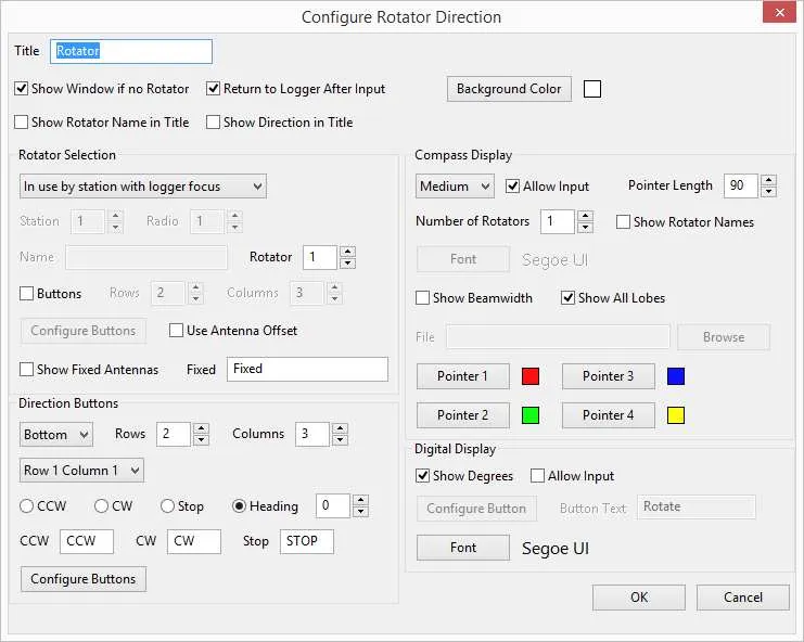
Set the Title text to the text you want to be shown in the title of the Rotator Direction window.
Check the Show Window if no Rotator box if you want the rotator window to stay visible if there is no rotator to display.
Check the Return to Logger After Input box if you want the keyboard focus to be returned to the logging program’s active radio entry window when a rotator direction is changed.
Check the Show Rotator Name in Title box if you want the rotator’s name to be displayed in the window title.
Check the Show Direction in Title box if you want the direction to be displayed in the window title.
Click the Background Color button to set the background colour.
Rotator Selection
Section titled “Rotator Selection”There are several choices for selecting which rotator to display.
If the choice specifies a station then antenna beamwidth, offset, and number of lobes are available. A station can be specified by station and radio number or as the station with logger focus.
The choices for station with logger focus only work properly if the client is running on the same PC as the logging program and is running the logging program interface.
It is possible that any of these choices will match more than one rotator. If this happens rotator selection buttons can be used to select one of the rotators, or the rotator number can differentiate between them, or the compass can be configured to show more than one rotator.
These are the choices:
- Select All if you want to show all rotators.
- Select By Name and fill in the Name if you want to show a specific rotator.
- Select Available for specified station if you want to show the rotators which are used by the available antennas for a specific station. Set the Station and Radio to the station and radio to be displayed.
- Select In use by specified station if you want to show the rotators for the antennas selected by a specific station. Set the Station and Radio to the station and radio to be displayed.
- Select Available for station with logger focus if you want to show the rotators used by the available antennas for the station that has logging focus.
- Select In use by station with logger focus if you want to show the rotators for the selected antennas for the station that has logging focus.
Set the Rotator to the number of the selection that should be used. For example if it is set to 1 the first rotator selected will be used and if it is set to 2 the second will be used. If the station has more than one rotator which will be shown it is possible to create several Rotator Direction windows, one for the first rotator, one for the second, etc.
Rotator Selection Buttons
Section titled “Rotator Selection Buttons”If you want to select the rotator by using a grid of buttons:
- Check the Buttons box.
- Set the number of Rows and Columns for the buttons.
- Click Configure Buttons to display a dialog where you can set the size, shape, colours, and font of the rotator selection buttons. See Button Configuration for details.
Check the Show Fixed Antennas box if you want to show the direction of a fixed antenna if no antenna with a rotator will be shown. Set the Fixed text to the name to be displayed when a fixed antenna is shown. This is only available when the rotator is selected if the antenna choice specifies a station.
Direction Buttons
Section titled “Direction Buttons”Direction buttons can be placed at the top, bottom, left, or right of the direction indicators.
If you want to display direction buttons:
- Select Bottom, Left, Right, or Top.
- Set the number of Rows and Columns.
- For each button:
- Select the Row and Column, for example Row 1 Column 1.
- Select CCW, CW, Stop, or Heading. If you select Heading set the number of degrees for this button.
- Set the text for the CCW, CW, and Stop buttons.
- Click Configure Buttons to display a dialog where you can set the size, shape, colours, and font of the rotator direction buttons. See Button Configuration for details.
Compass
Section titled “Compass”If you want to display or change the direction of rotators using a compass:
- Select Small, Medium, Large, or Custom.
- If you selected Custom then select a File, either by typing in the file specification or by clicking the Browse button and finding it. The file must be a Portable Network Graphics (PNG) file. It should be square. The size of the file will determine the display size.
- Click Allow Input if you want to be able to change the direction of the antenna by clicking on the compass.
- Set the Pointer Length. The number is the percentage of the distance from the centre to the edge of the compass. The default is a good choice for the supplied compass. If you supply a custom image you may want to pick a different length.
- Set the Number of Rotators to the number of rotators you want to display on the compass. The maximum is 4.
- Check the Show Rotator Names box if you want the rotator names to be shown below the compass. If input is allowed and more than one rotator can be shown, a check box will be placed to the left of each rotator name. If the box is checked that rotator will be turned when the compass is clicked.
- Click on Pointer 1, Pointer 2, Pointer 3, or Pointer 4 to set the colour of the pointer.
Degrees Display
Section titled “Degrees Display”If you want to display the direction as a number or to type a number to change the direction:
- Check the Show Degrees box.
- Check the Allow Input box if you want to be able to enter a heading. Click Configure Buttons to display a dialog where you can set the size, shape, colours, and font of the rotate button. See Button Configuration for details. Enter the text for the rotate button in the Button Text field.
- Click the Font button to select the font, size, and colour of the direction display.
Button Configuration
Section titled “Button Configuration”The dialogs for the Rotator Selection Buttons, the Direction Buttons, and the Rotate Button are the same except for the window title:
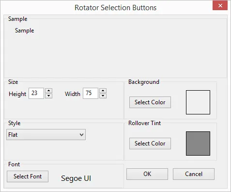
Set the Height and Width to the desired size.
Select Flat, Flat Rounded, Flat With Border, Flat Rounded With Border, or 3D to choose the button style you prefer.
Click the Select Font button to set the font, size, and colour of the button text.
Click the Select Color button in the Background box to choose the colour the button should show.
Click the Select Color button in the Rollover Tint box to choose the colour to tint the button when the mouse cursor is on it. Usually a light or dark grey is appropriate but any colour can be used. It is currently not possible to tint a pure white button.